


By Chaz Andrews, Technical Manager of Doepke UK
Inverter speed controlled pumps and compressors circuits require specific types of RCD. The characteristics of the equipment will determine if you require Type F or Type B RCDs and any associated restrictions on RCD sensitivity. Check with the manufacturer before quoting for the installation.
Equipment design characteristics
Appropriate planning at the quotation stage saves time and unforeseen expenses on site at a later date. The installation design, equipment to be connected and any RCD requirements including the ‘Type’ and ‘Sensitivity’ must be considered together, not in isolation.
Equipment may be self-contained for small installations or have sperate units with standalone inverter drives for larger installations. Inverter based equipment connected to three-phase supplies, that does not include an isolating transformer (see manufacturer’s information) can only be used with type B RCDs – see BS 7671 531.3.3. This is explained in detail in Doepke Techpub-17 – http://doepke.co.uk/download/download.html.
For single phase equipment, the use of type F or B RCDs is governed by the level of smooth dc residual current produced under certain fault conditions. This fault current is related to the value of the “dc link voltage” (see below) i.e. it is function of the equipment design.
The operational leakage current (PE current), must be compatible with the installation design and associated RCD sensitivity – see 531.3.2. Take into account the possible addition of leakage currents when adding new equipment to an existing installation. The addition of three-phase non-linear loads increases the harmonic content and associated leakage currents – see PDS (Power drive system) – RCD Sensitivity.
DC link voltage – Type of RCD
Figure 1 (below) gives a generic example of a single phase combined compressor and fan unit. The dc voltage output from the rectifier will be a minimum of 1.41 x ac rms voltage. Some designs may have a step-up voltage section, to increase the dc voltage, before it is fed into the control section. A capacitor connected across the dc bus provides a power reservoir (smoothing), for the control section during the non-conducting period associated with the AC supply. A fault to earth on the dc link section results in a smooth dc residual current flowing in the PE conductor, back to the source earth and returning via the line conductors through any upstream RCDs.


For smooth dc residual current < 10 mA (defined by the manufacturer of the equipment), you can use Type F RCDs – see BS7671 531.3.3 (iii) Note 2.
For smooth dc residual > 10 mA or it is not defined i.e. the manufacturer does not specify the type of RCD, 531.3.3 (iv). Note 3 refers to the use of type B RCDs.
PDS – RCD sensitivity
Elements of the PDS and the associated environment e.g. filters, inverter, motor cable, motor, existing supply quality, harmonics and ambient conditions, determine the total leakage current present during fault free operation of the equipment. This results in the fluctuation of the leakage current, consequently 531.3.2 (ii) recommends that you do not exceed 30% of the RCD sensitivity to achieve reliable operation of the equipment.
Type F and Type B RCDs are designed to respond to the sum of the leakage / residual currents generated at various frequencies by inverter controlled equipment – see Figure 2 (below). Before making a final selection and purchasing equipment, check the installation manuals to verify the type of RCD and the minimum sensitivity requirements. If it is not in the manual, ask the supplier to provide this information before you purchase.
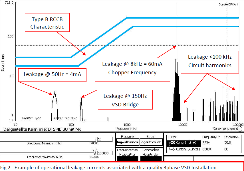

Operational leakage currents
BS7671 543.7.1 places limits on the operational leakage current, based on the method of connection:
Conventional 13 amp plug <3.5 mA and suitable for connection to a circuit protected by the appropriate Type of 30 mA RCD.
Equipment with leakage currents > 3.5 mA requires permanent connection to the supply, or the use of 60309-2 plug and socket – see 543.7.201. This equipment may not be compatible with the appropriate Type of 30 mA RCD. Relatively small inverter setups may require a minimum of 300 or 500mA RCDs, but check first – don’t make assumptions.
See 531.3.2 with regard to the design of the installation to avoid unwanted tripping. Note the points about the accumulation of earth leakage currents and consideration for separate feeder circuits, protected by the correct Type of RCD i.e. you cannot install Type F or B RCDs down stream of Type A or AC RCDs.
Conclusion
Check the details first – don’t guess or make assumptions.