


DEHN UK’s Robin Earl undertakes a comparison of type 1 surge protection devices and looks at the implications thereof.
Not all surge protection devices are created equal – some are more equal than others!
The whole purpose of fitting surge protection devices (SPDs) in an electrical installation is to limit the voltage that the sensitive equipment could see, to a level that will not damage the installed equipment.
The SPD has a declared voltage protection level (Up) and this value must be below the withstand voltage (Uw) of the installed equipment or appliance.
If Up is higher than Uw then damage can still occur, so the SPD needs to be changed or located closer to the end load as there is an additional inductive voltage that appears over cable lengths of 10m or more.
10m rule
Referencing BS7671, in regulation 534.4.4.2, we find the 10m rule and this describes the effect of the surge device output voltage Up doubling over this distance, hence the requirements for additional SPDs to ‘knock’ the surge voltage down again to below the withstand level.
This then brings up an interesting point about the energy coordination between the SPD and the end load, as it is not just about the voltage let through.
There are two types of type 1 SPD, defined by the components within the device.
There is the metal oxide varistor (MOV) and there is the spark gap. Let’s have a look at the make-up of each and how they function. First, MOVs are semiconductor devices made of zinc oxide with a ceramic-like structure. When the voltage across an MOV exceeds its rated threshold (clamping voltage), it starts conducting current, effectively diverting the surge current away from sensitive equipment and to the ground. They have a nonlinear voltage-current characteristic, meaning their resistance decreases as the voltage across them increases and are typically used in low to medium-energy surge situations, providing a quick response to transient surges. However, MOVs have limited capacity to handle large surge currents, especially when dealing with repeated or sustained surges. Over time, they may degrade due to the energy absorbed during surges, potentially requiring replacement.

The alternative type 1 SPD relies on spark gap technology. These devices are simple, robust and reliable, consisting of two conductive electrodes separated by a small gap filled with a gas or air. When the voltage across the spark gap exceeds a certain threshold (sparkover voltage), the air or gas ionises, causing a spark to jump the gap and creating a low-resistance path for the surge current.
Typically, spark gaps provide very fast response times and are capable of handling extremely high surge currents, including those generated by direct lightning strikes.
Unlike MOVs, spark gaps have a wave breaking characteristic, meaning their resistance collapses as the voltage across them increases, and they present as a short circuit.
Spark gaps are commonly used in high-energy surge situations where the surges are too large for MOVs to handle effectively. This is important as all equipment worth protecting already has an MOV inside as its inherent over voltage control measures. This appears in the standard BS EN 61000-4-5 to determine the voltage that equipment will withstand. As previously explained, all MOVs work in much the same way; they just get bigger to deal with higher energy and current values.
The power supply for the screen on your PC has MOVs within it; they smooth over the peak of the surges that appear in the mains supply.
All about coordination
However, what is very difficult to predict is what happens when you install a MOV-based type 1 SPD with the small MOVs in the power supply. This becomes a coordination of energy issue, and this impacts all SPD installations.
In BS7671 we find the following text in 534.4.4.5: ‘SPDs shall be selected and erected such as to provide coordination in operation by reference to the manufacturer’s data’.
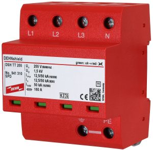
In, for example, the DEHNshield datasheet, a spark gap-based type 1 SPD in the 941 series family of products, we can see that the SPD offers type 1, type 2 and type 3 energy coordination up to 10m away.
So, we could wire the display screen or any other end equipment into the SPD directly and be confident that the output of the DEHNshield will not be so high as to damage that equipment. Essentially, we have energy coordination. So, we declare this information and we also have type 1 SPDs for specific applications like EV charging points – the Emob SPDs – and those SPDs again have energy coordination to 10m but, in addition, less than half a joule of energy is let through.
This is critical in those compact installations when short distances between the SPD and the equipment brings energy coordination issues.
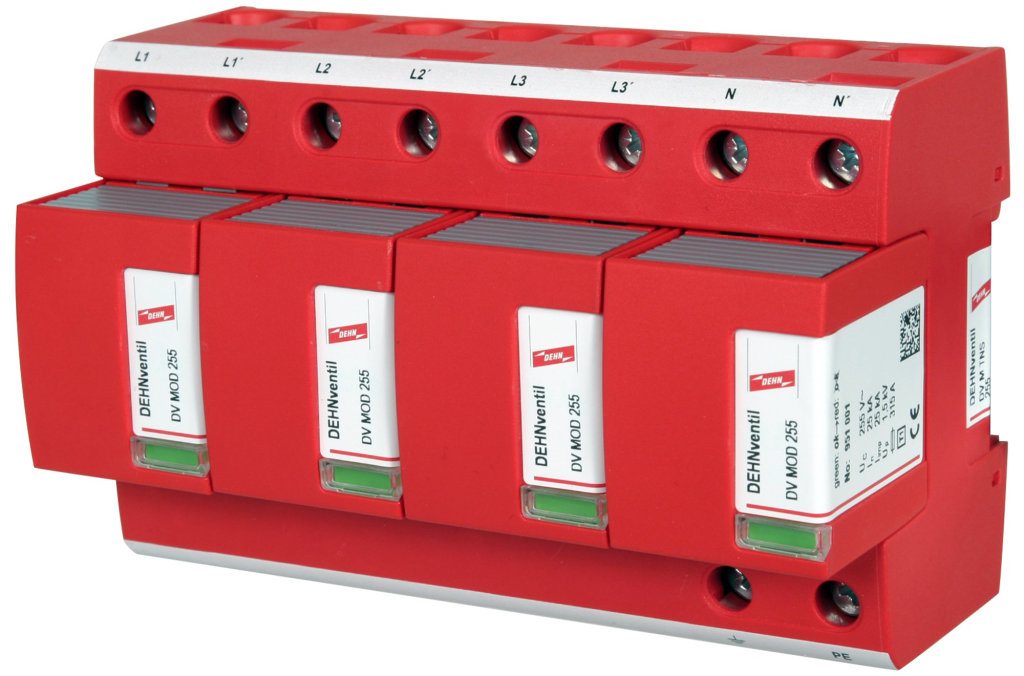
So, what of the type 1 MOV SPDs? Looking at the datasheets, we do not see either an energy coordination distance or a value of what energy is let through to the end equipment.
It is not possible to determine a figure when coordinating the MOV of the SPD to the MOV in the end load. The smoothing action of the MOV does not limit the energy low enough to ensure protection within close cable distances in EV charging points, for example, or in switchgear that has measuring and metering equipment or monitoring devices.
Graphic illustration
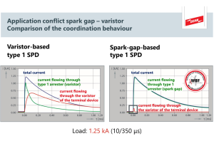

In Fig 1 we see a blue line for the surge current entering the system going to the end equipment. The green line on the left-hand side shows the current through the type 1 MOV SPD, which has taken out the worst of the surge.
The red line is the current that does get to the end load. Clearly this can be too much, and the end load can be damaged, especially if the cable distance is within that 10m as there is no energy coordination.
Now to the spark gap type 1 SPD on the right-hand side. Again, we see the blue line showing the same surge current into the system and the green line is the current through the SPD; the difference is the red line that shows the current to the end load. This is a far lower current; in fact, so low that even equipment connected to the SPD directly will not see enough energy to damage it.
The difference is that the spark gap acts like a binary switch – it is normally open circuit and then, in surge events, it’s a short for the surge current to earth. That small blip in the red line is the dwell time for the SPD turning on and that’s it.
It is for this reason that DEHN does not produce MOV-based type 1 SPDs due to the inability to state that energy coordination is possible at all distances and that the number of joules that can be transmitted to the end loads could be way too high.

Just to remove any doubt or perceived bias, the commentary above and the graphs are based on actual experiments conducted in a lab to compare the performance of the two types of type 1 SPDs.
In both cases, the cable connections were very short and the lightning impulse value was 12.5kA. The outcomes were significantly different. In the MOV test, the varistor representing the end load was destroyed totally and in the spark gap test there was no damage at all to the varistor end load.
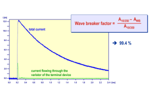
In these tests, up to 99.4% of the impulse current is diverted to ground due to the action of the spark gap design.
So, as previously mentioned, not all surge protection devices are created equal – some are more equal than others!