


By Chaz Andrews, Technical Manager of Doepke UK
Applications for inverter speed controlled water pumps associated with RCD protection can be challenging, even for companies and staff with specialist design experience and knowledge.
Site Survey First / BS7671
Using general purpose inverters for variable flow rates in irrigation, aeration, drainage, level control etc may not require 30 mA protection. Carry out a site risk assessment and check if the application is covered by Section 702?
For example, fountains and ornamental ponds require the use of specifically designed pump sets meeting BSEN60335-2-41. If you are planning to use RCDs – ref Reg. 702.410.3.4.2 (ii) as a protective measure, check that the pump and controls are suitable for use with a 30 mA RCD and the Type of RCD required – see Regs 415.1 and 531.3.2.
The individual items of equipment and the installation layout impact on the levels of operational leakage current and, consequently, the selection of the appropriate RCD sensitivity to prevent unwanted tripping.
If it is an existing installation containing an RCD and you intend taking the supply from this device, the Type of RCD must be compatible with inverter manufacturers RCD recommendations. For example, if the main RCD is supplying a farmhouse or domestic premises with a 300 mA limit (see Reg. 532), and the inverter requires a 25A 300 mA Type B RCD. It may be cost effective to consider a separate feeder circuit, as compared to replacing the main incoming RCD with a Type B – see Fig 1. Running the pump on a separate circuit reduces the chances of problems with the existing PE circuit and the addition of leakage currents associated with the main installation.
Note: Standalone inverters used with separate pump sets may not be suitable for use with 30 mA RCDs.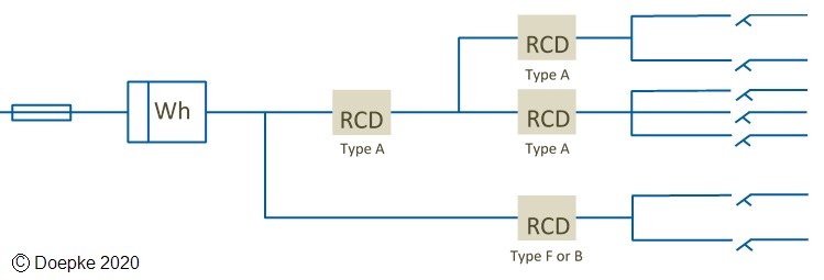
Operational leakage current
Leakage currents flow to earth as a result of capacitors in the EMC filters , DC link, output filters and the parasitic capacitance associated with cabling and the pump motor – see Fig 2. The RCD will be subjected to the arithmetic sum of the operational leakage currents and must be rated taking this into account. Check the Inverter Manufacture’s installation instructions or ask them to confirm the minimum RCD sensitivity and type, before finalising the installation design, costings and purchasing any equipment.
Note: To avoid unwanted tripping see Reg. 531.3.2: The sum of the PE currents should not exceed 30% of the RCD sensitivity.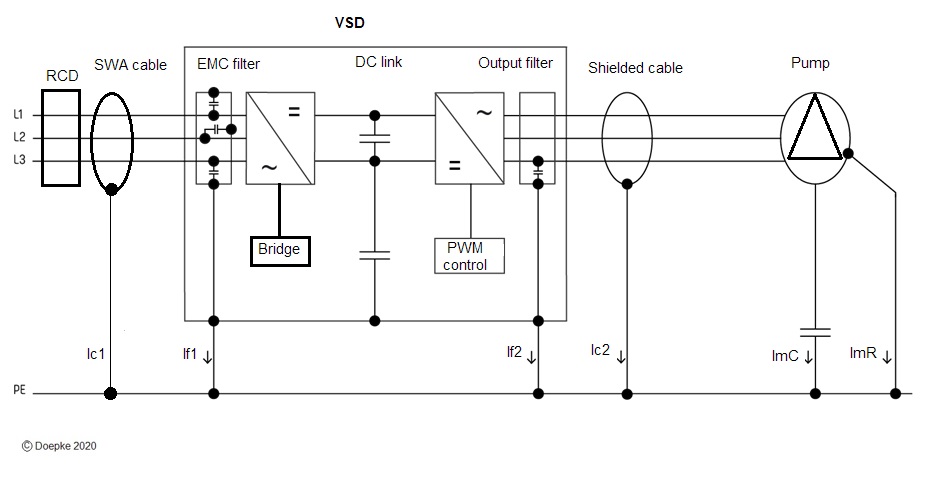
Inverter Cables / Filters / Switching frequency
Manufacturers perform EMC tests with a specified cable length between the inverter, filter and motor – see Figure 3. This gives three examples for different kW ratings based on the manufacturer’s test data.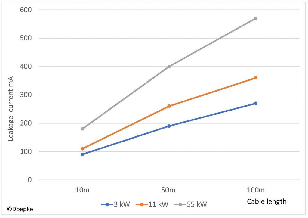
Increasing the cable length increases the leakage current, impacts on the performance of the EMC filter, life of the motor and for lower kW ratings, an allowance must be made for the cable losses. Check with the manufacturer on the maximum recommended cable length, associated leakage currents and any requirements for output (Sine) filters. Changing the inverter switching frequency setting will change the leakage current.
External EMC filters must be correctly matched to the inverter, its switching frequency and motor cable lengths. Use the inverter manufacturer’s recommended filters or filters from a specialist filter manufacturer who has completed tests with their own filters and the inverter manufacturer’s products. The resonant frequency of the filter must not be equal to or close to the inverter switching frequency, as high leakage currents can flow in the resonant circuit created between the inverter and an external EMC filter. Currents circulating in a resonant circuit, created downstream of the RCD, do not pass through the RCD and can also result in dangerous levels of touch voltage – see Fig 4.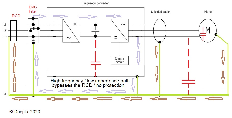
Note: To save energy, inverters may automatically reduce switching frequency to a lower level at low speed. If this feature is included in the control function, it must be taken into account with regard to filter selection.
Equipment characteristics and installation design
Standalone inverter drives and pumps require appropriate planning at the quotation stage. This saves time and unforeseen expenses on site at a later date. The installation design, equipment to be connected and any RCD requirements including the ‘Type’ and ‘Sensitivity’ must be considered together, not in isolation. Inverter based equipment connected to three-phase supplies, that does not include an isolating transformer (see Manufacture’s information), can only be used with type B RCDs see BS 7671 531.3.3. This is explained in detail in Doepke Techpub-17 – http://doepke.co.uk/download/download.html
For further information, visit www.doepke.co.uk or email sales@doepke.co.uk.